Camera And Radar Collaboration (Using Real World Location Transforms)
This Unity project was made during my work for a company called Echodyne. They create a portable and efficient radar and wanted my group and I to create a system to point a camera towards the objects that the radar picks up. My portion of that project was to do the actual camera pointing.
The project started with a previous attempt from 5 years prior, but the state of the project required a complete rewrite due to it not even running and the math involved being cobbled together. The previous version required the camera to be next to the radar and for the radar to be set up in a particular orientation. My version needed to support the camera being in any location on earth and in any orientation, regardless of the radar’s position or orientation which also needed to be unconstrained.
This particular project (the one being showcased) was made while I was trying to visualize and confirm if the math was working correctly. Due to the system needing to work before being tested in the real world, I needed to give a confident answer when asked if my portion of the project was working. This Unity project was my way of confirming everything. I also made a version of this in Python which only tested configurations that could be confirmed with simpler pure math.
The entire simulation is set in ECEF coordinates. The white lines are the radar’s ENU coordinate system. The light blue lines are the camera’s ENU coordinate system. The red, green, and blue lines are the camera’s XYZ coordinates found from the camera’s zero orientation. The blue sphere is the radar’s location. The red sphere is the camera’s location. The yellow sphere is the target location and the yellow line is the direction the camera must face in order to be looking toward the camera.
In the video below, I manipulate the target’s ENU coordinates from the radar, the radar’s LLA coordinates, the camera’s YPR orientation, and finally the camera’s LLA coordinates. This is to show that the system can truly work in a global system with the radar and camera being on literal opposite sides of the earth.
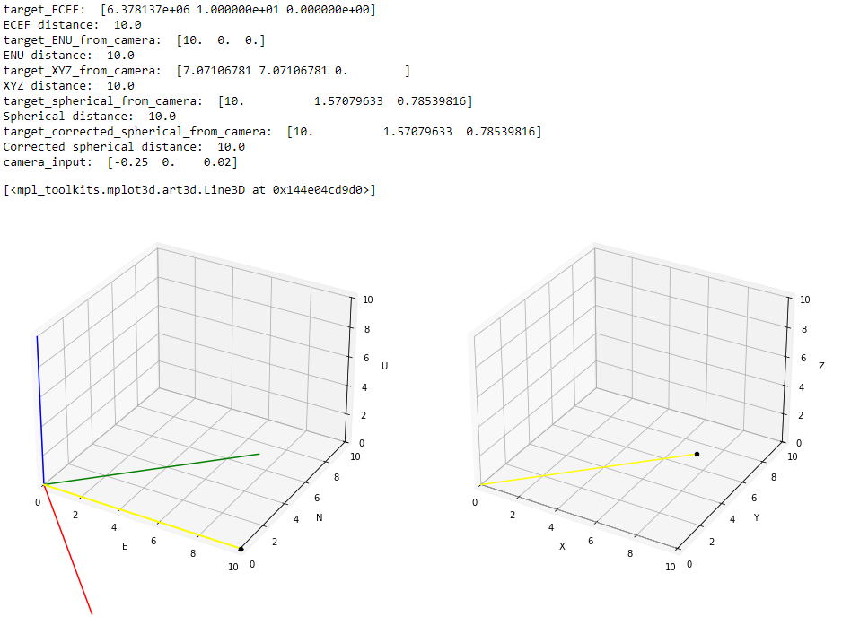
The image below is the version that I created in Python. This is a single test case where the yaw is -45 degrees. The text is the output shown by the graphs and the spherical and input data that would be used to actually steer the camera.
The left graph is the original ENU coordinates of the camera with the target location being marked in black and the yellow line is the direction the camera must face. The red, green, and blue lines and the east, north, and up coordinates when rotated based on the input yaw, pitch, and roll, resulting in an x, y, and z coordinate system.
The right graph is the new XYZ coordinate system with the target location and camera direction relative to the camera’s zero orientation.
Below is a video of the system capturing the location of the boat and pointing the camera toward it. The radar being used is not very accurate, so the position being relayed to the system is not always perfect and so the camera jitters. There is also an instance in this video where the position of the boat seems to veer off to the right and the camera tries to track it. When the track corrects itself, the camera moves back to have the boat in frame again.
The video also demonstrates the UI that a member of my team worked on. The controls present on the top right are my contribution to the UI as I was responsible for everything regarding camera controls.
